Presence Monitoring System
First, a little back story for this project.
Context
The floor of the building where the Programming Languages and Compiler Construction Group of CAU Kiel is located uses door signs to indicate whether each staff member is currently present, working somewhere on campus or has left for the day. The sign has multiple fields and a magnet marks the current status.
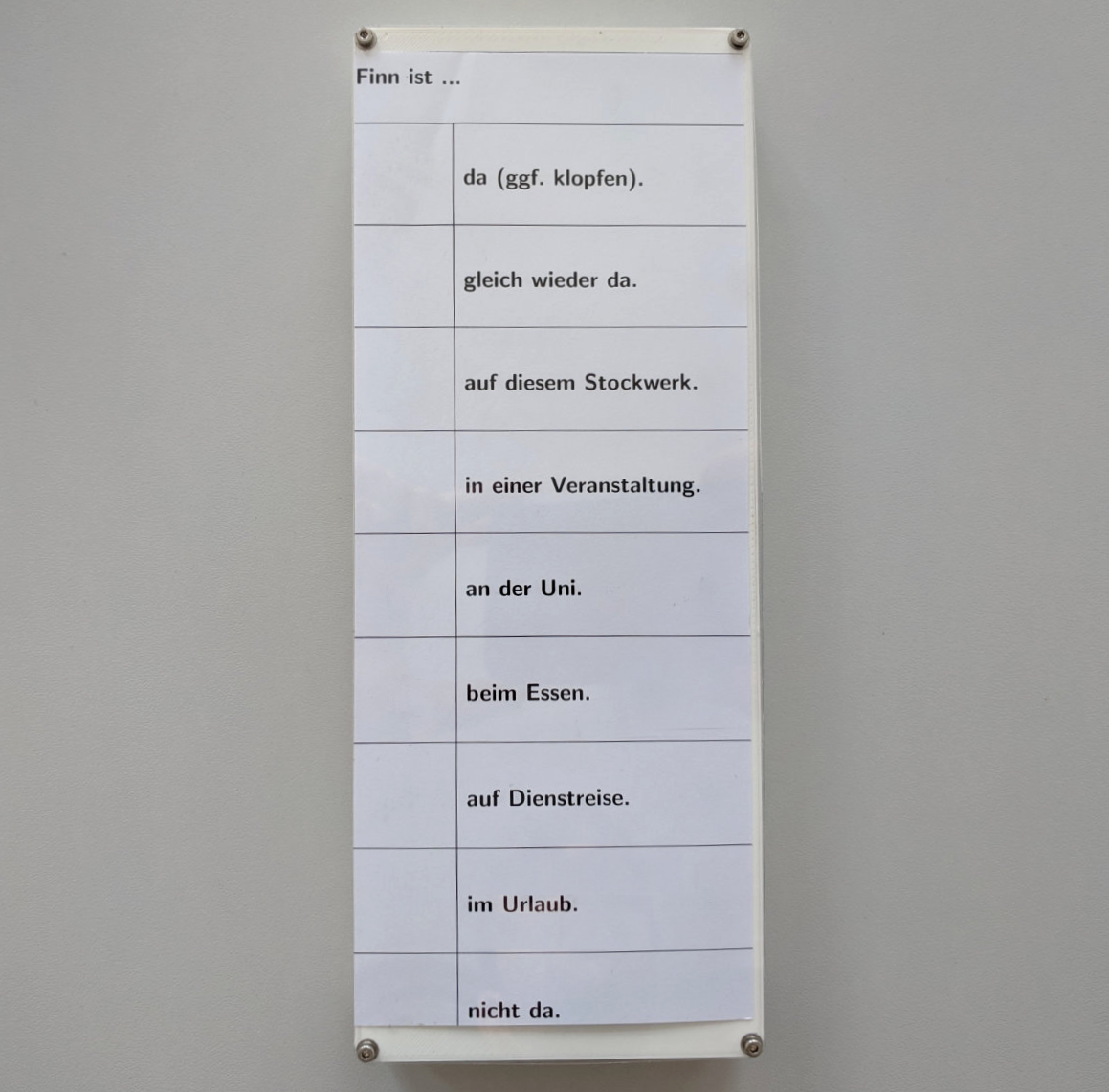
Although this solution is sufficient, visitors have to walk up to the desired office in order to find out if the respective person is currently available. In March 2018, Bennet Krause developed a distributed presence monitoring system as part of his bachelor’s thesis.
Based on Arduinos and NRF24L01 wireless modules, each sign senses the position of the magnet using hall sensors and then transmits the information to a central server that renders a webpage with all staff’s presence status. The page is shown on a central display located next to the elevator and can be accessed from within the university network.
The concept was implemented a few months later by building prototypes of the digital signs and the server infrastructure. The circuits were built from perfboard, where each connection was made by hand-soldering a correctly sized wire to the components. Similarily, the enclosure was hand-cut from a sheet of foam. Although these prototypes were mostly functional, the construction was cumbersome and not very reliable.
Designing PCBs
In order to reduce the amount of soldering involved in building the door signs, we decided that professionally printed circuit boards were the best option. Although schematics were part of the original thesis, only the wires and solder connections of the perfboard were shown. Thus, the schematics needed to be transferred to a tool which allows creating the necessary output files for PCB manufacturers.
As a novice in this area, I searched for suitable – preferably open source – options and found KiCad. KiCad is a cross platform and open-source electronics design automation suite which is more than sufficient for this project.
The first step was to create the new schematics. The original prototypes used a single PCB to house the logic and sensor components. To minimize the PCB area and thus, the costs, the schematic was split into two parts which are connected by a 10-pin cable.
The KiCad guide on txplore.com is a great resource for learning how to create PCBs. At this point, the schematics looked as follows.
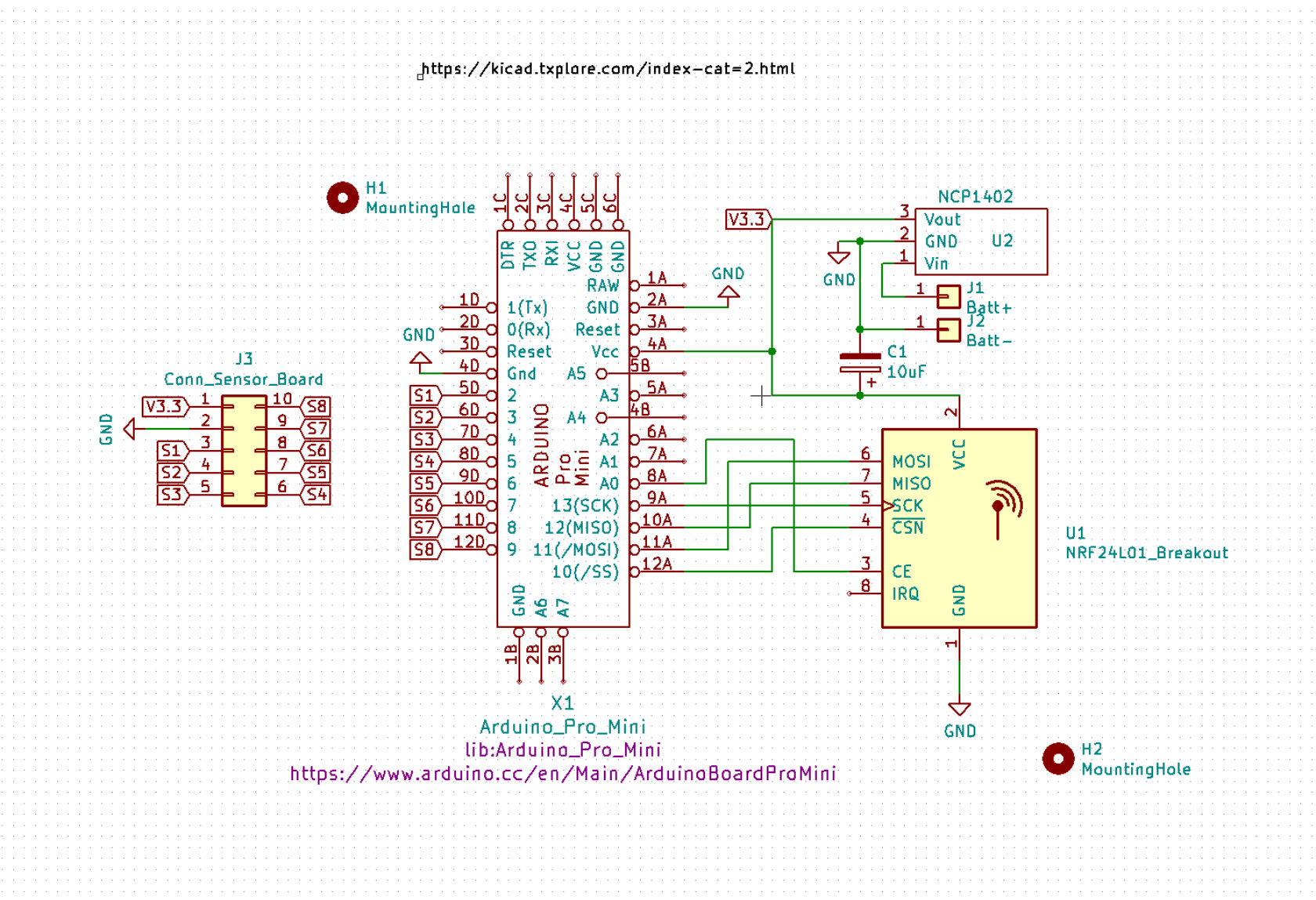
Although schematics are an important part of a PCB, they are only an abstract representation of the connections between the individual parts. In order to create a PCB, the components and the connections need to be physically arranged. Depending on the complexity of the schematics, the physical PCB has one or more layers. For simple designs, two layers are sufficient.
In the following image, the different layers are represented by green (underside) and red traces. Red marks signal traces that do not need to supply much power and thus, are not very thick. The green traces, on the other hand, connect power to the main components are sized appropriately.

Based on these specifications, the PCBs were ready to be professionally manufactured. With careful observation, the connections from the above diagram can be spotted on the PCB.
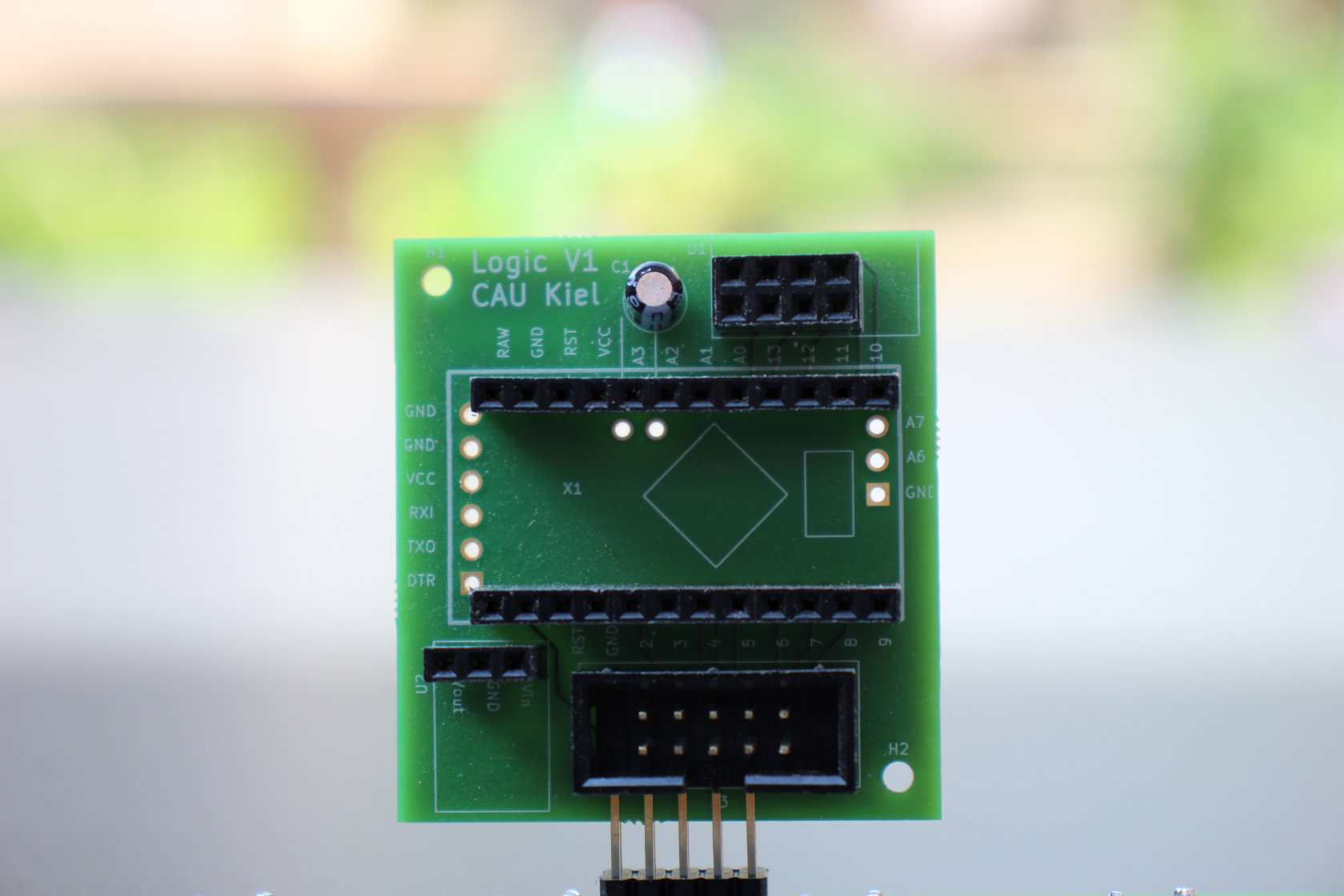
The traces are easier to see on the underside of the PCB.
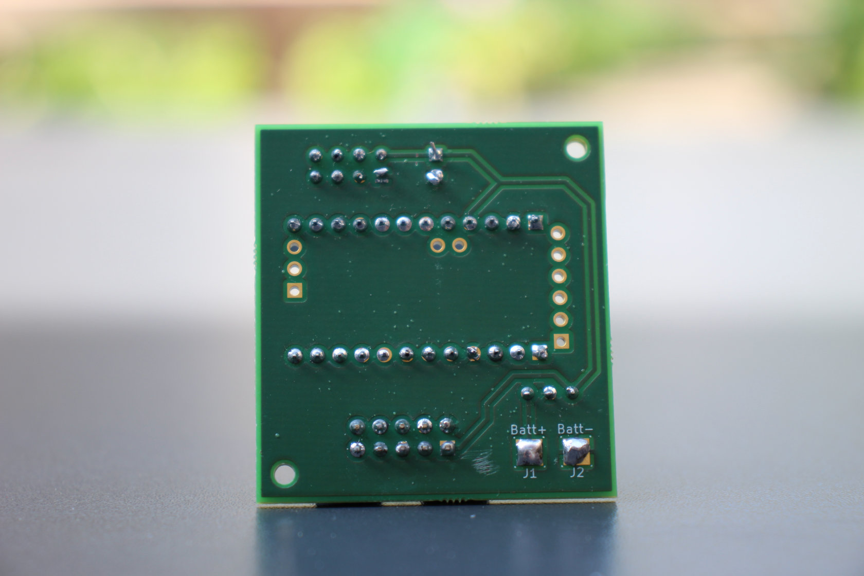
For the PCB holding the hall sensors, the male version of the 12-pin connector was used to connect eight hall sensors to the logic PCB shown above.
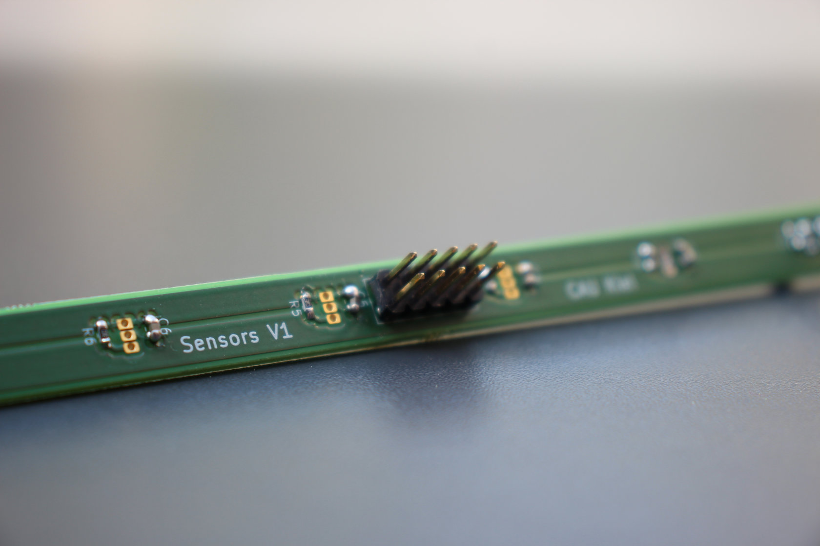
Again, one plane carried the power traces and the other the signal connection. The sensors were mounted on the opposite site to be able to screw the sensor board into the enclosure while still being able to access the connectors.
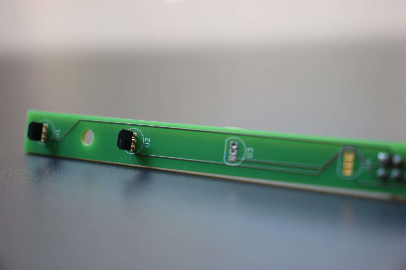
There were some minor problems with the initial version of the PCBs, but for my first PCB design, I didn’t expect a perfect board. In the second revision, these problems were fixed and a few design improvements were made. Finally, this part of the project was finished.
3D Printed Enclosure
The prototype’s enclosures were built from foam sheets and hot glue and, consequently, not very sturdy. Since I own a 3D printer and have experience in computer-aided design, I suggested printing the enclosures.
As a first step, the dimensions of the original enclosure were measured and then transferred to Fusion 360. Many revisions later, the resulting design looked as follows.
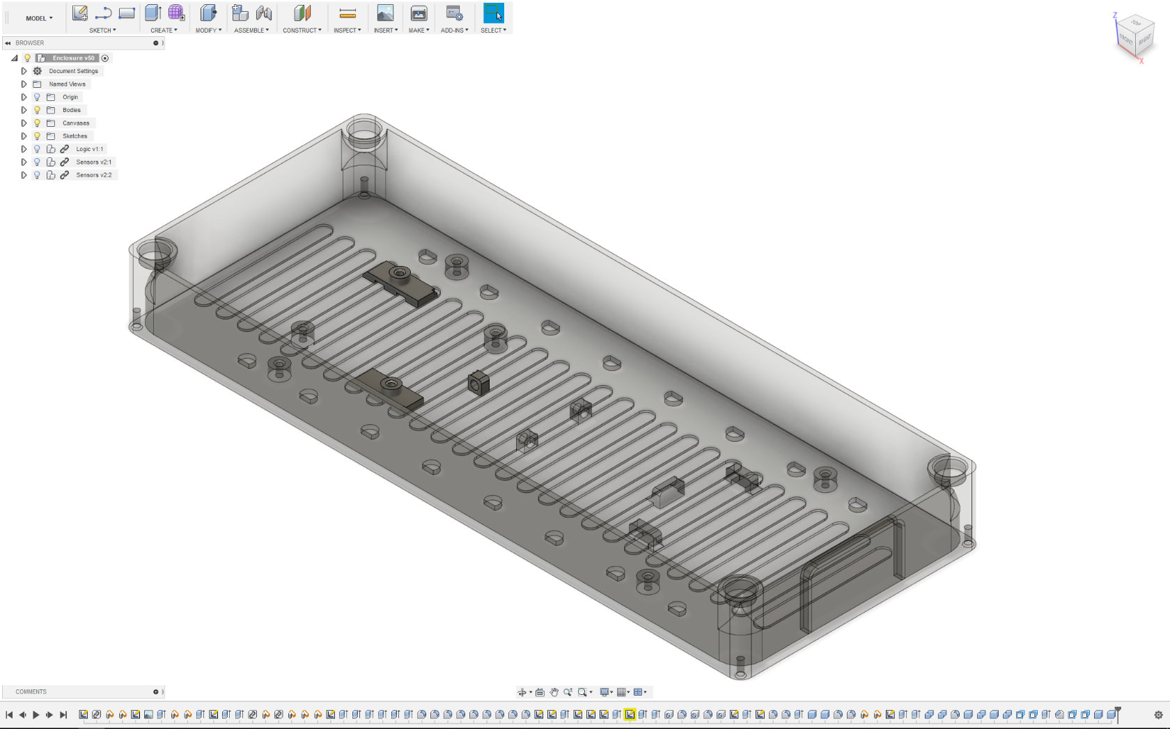
The design iteration began with a basic, rectangular design that features cutouts for the sensors and a few screw mounts. Additionally, each corner has a mounting hole for a magnet that allows attaching the enclosure to the magnetic door frame.

The second major revision was optimized in regard to weight since the initial version had quite thick walls. Unfortunately, the outside of the enclosure looked not very appealing and the printing time increased, so this approach was scrapped for the walls and only kept for the bottom of the enclosure.
To make the enclosure look a little nicer, the corners were rounded (please don’t sue me, Apple). Functionality-wise, a few more mounting clips for cables and the batteries were added.
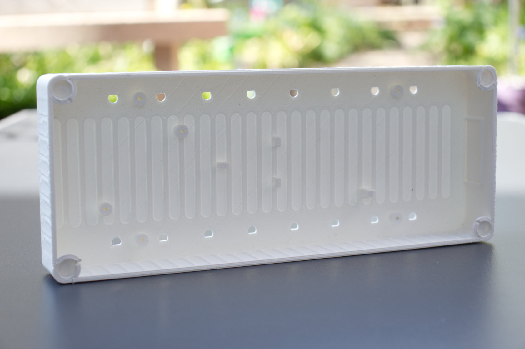
For the final version, a single layer of plastic was added to cover the sensor holes in order to simplify assembly. With an improved battery mounting solution and a few more mounting holes for reorienting the logic board due to wireless interference, the following enclosure satisfied all requirements of the project.
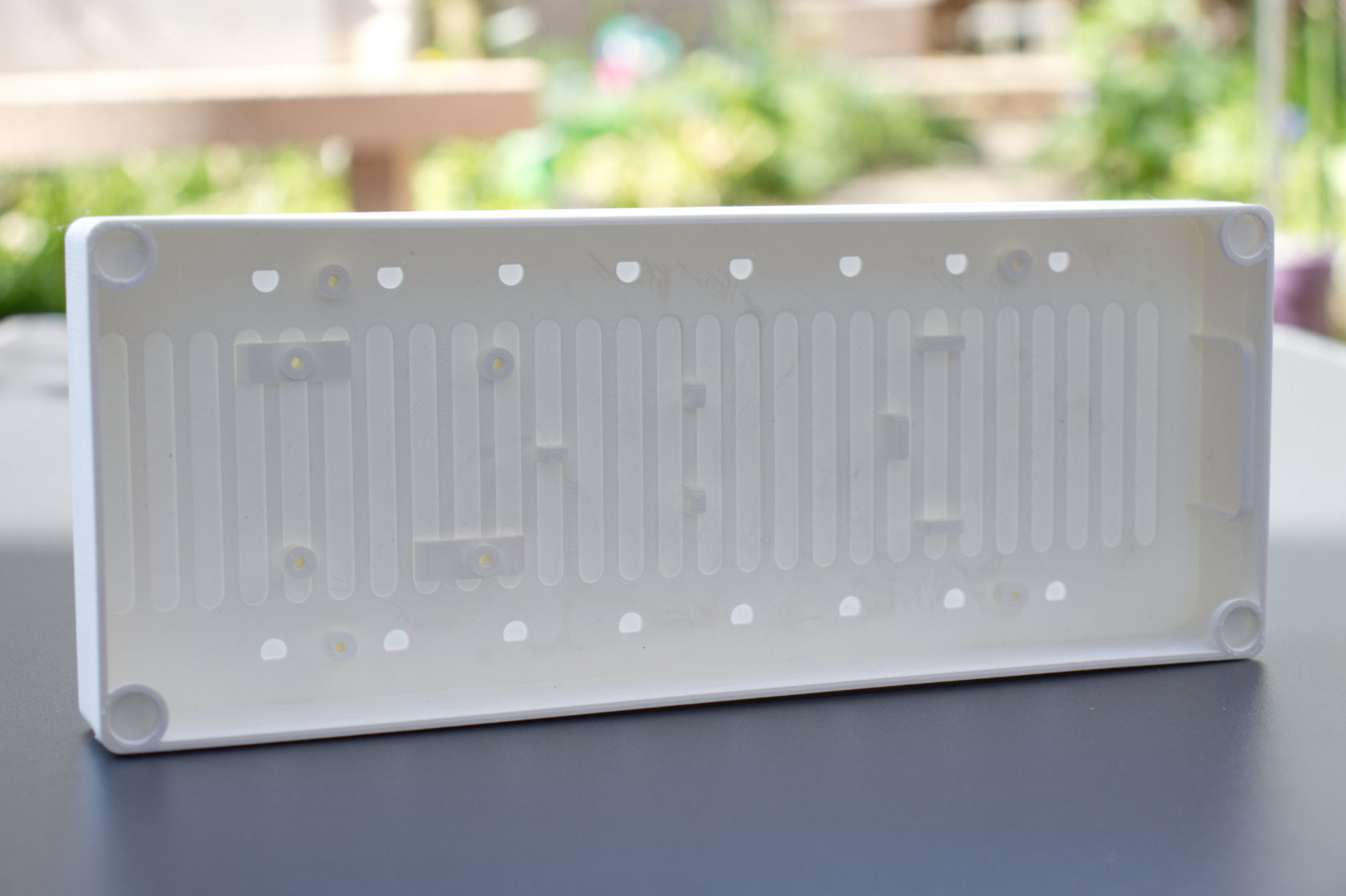
With about 2.5 hours printing time and about 70g of filament needed to print the enclosure, this approach proved to be simple and cost-effective. A few (involuntary) drop-tests later, the construction also seems to be quite sturdy.
With the electronics mounted inside the enclosure, a presence monitoring door module now looks as follows.
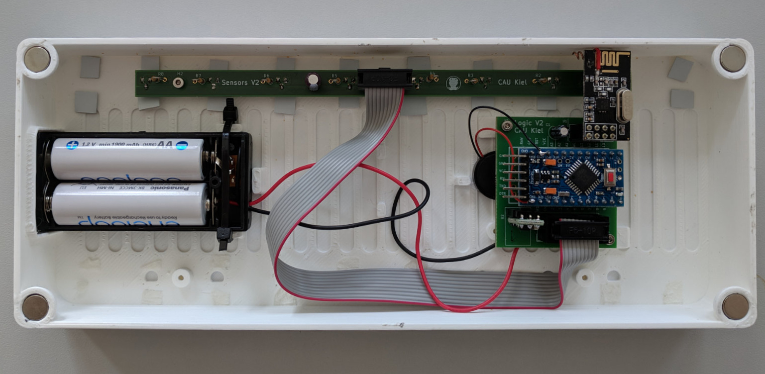
Originally, the wireless module (the board with golden antenna traces that look like a snake) was supposed to be at the top of the module. While testing the system, however, we noticed that the wireless module worked much better in a sideways orientation. After experimenting with a few different antenna designs, the wireless modules were also modified to use a custom dipole antenna with curled wires. Finally, a small buzzer was added to signal the user when a status switch was successful.
Through various optimizations along the design process, the door modules now last over a month on one battery charge, compared to a few days in the worst case. When more modules are needed eventually, a few more PCBs and enclosures can be ordered and assembled easily. Project successful!
